Logo

Thiagarajar College of Engineering
Department of EEE

Power Electronics Virtual Laboratory

AC Voltage Controller - Introduction

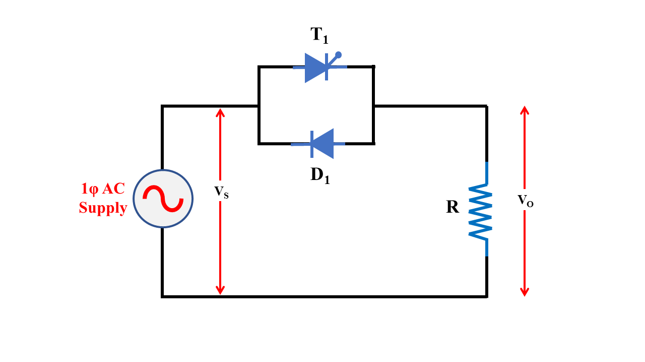
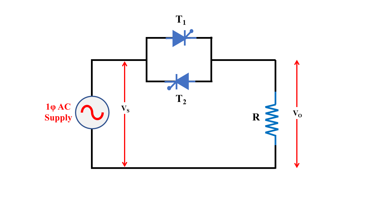
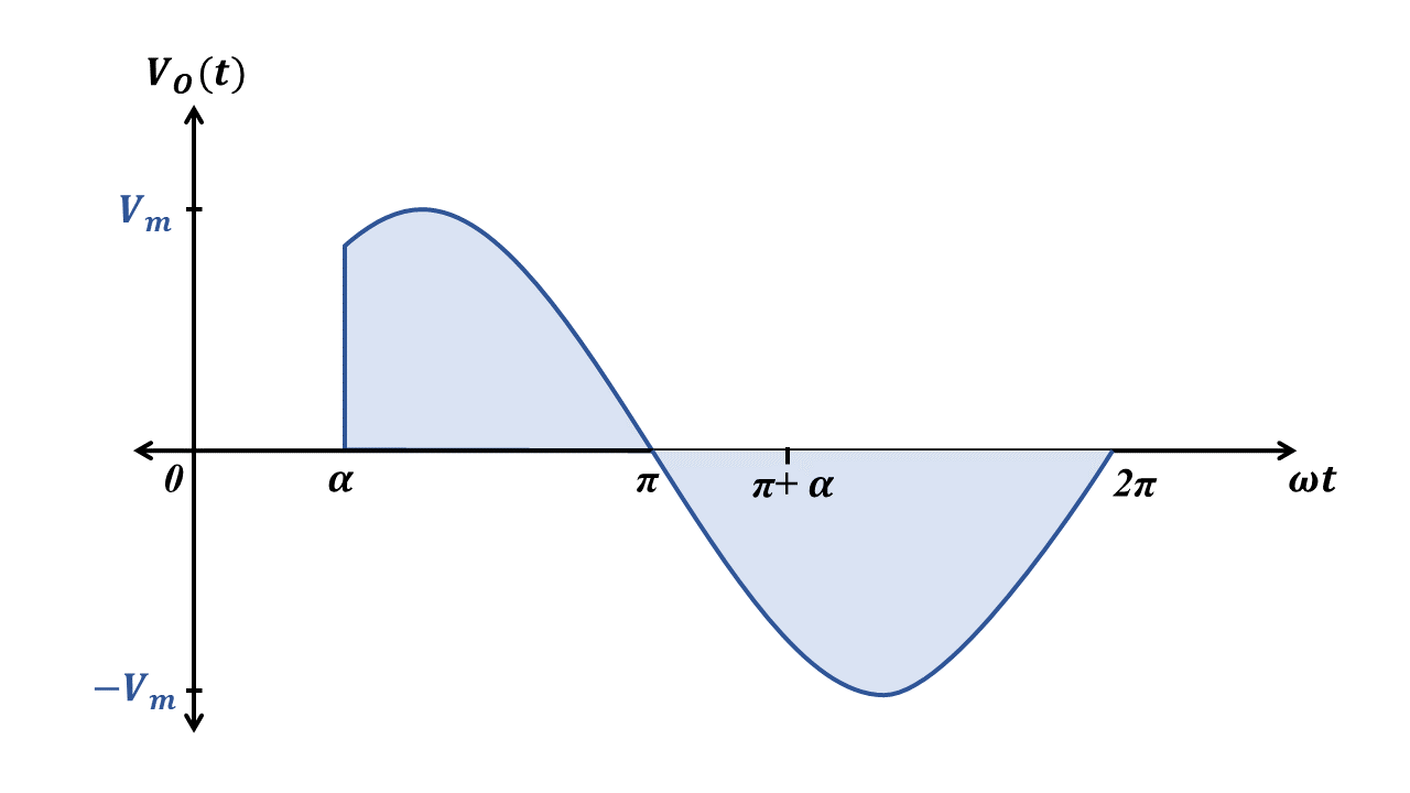
Types of Phase Controlled AC Voltage Controllers

Half wave voltage controller Full wave voltage controller
It has one SCR and one diode. So anyone of the half cycles can only be controlled. It has two SCRs so both the half cycles can be controlled.
Since both the half cycles are not symmetrical, a dc component is introduced, which is undesirable. DC component will not be introduced if the firing angles of both the SCRs are equal.

Additional Theory

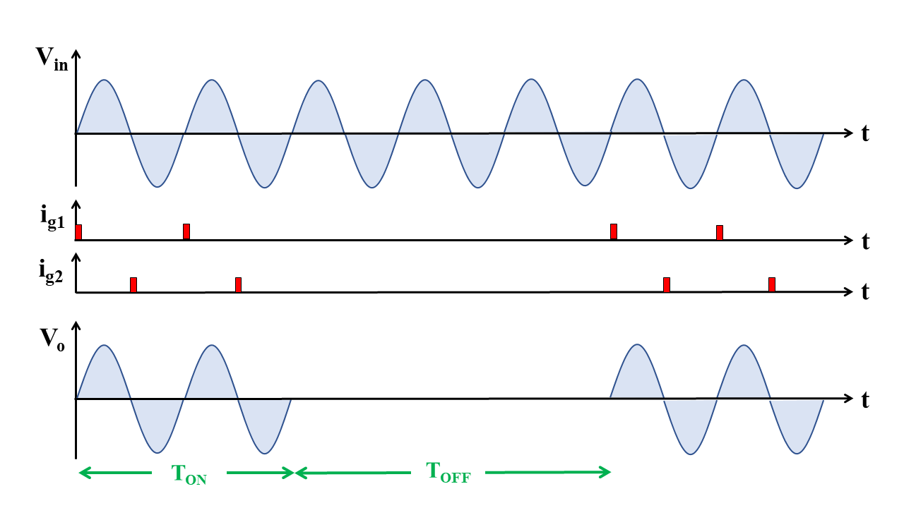
Integral Cycle Control
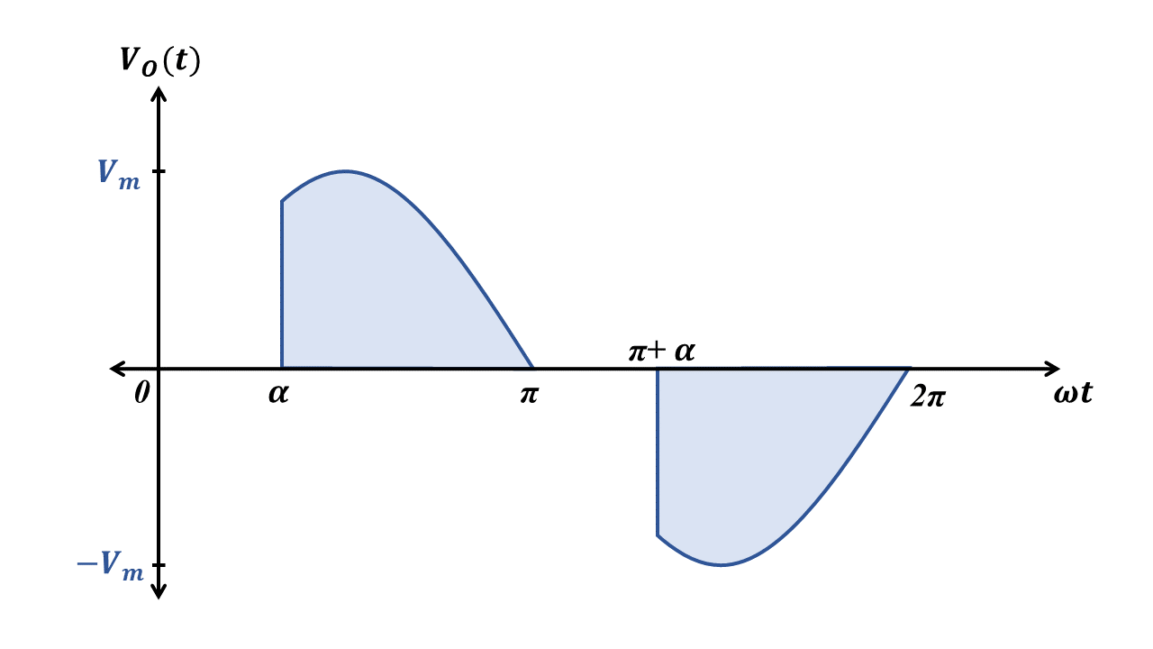
Cycle control waveform diagram
  • Integral cycle control consists of switching on the supply to load for an integral number of cycles and then switching off the supply for a further number of cycles
  • This control technique is used in applications where mechanical time constant or thermal time constant is of the order of several seconds.
  • For example, mechanical time constant for many of the speed-control drives or thermal time constant for many of the heating load is usually quite high. For such applications, almost no variation in speed or temperature will be noticed if control is achieved by connecting the load to source for some on-cycles and then disconnecting the load for some off-cycles
  • The equation of output RMS voltage is given below.
  • where, n indicates the number of on-cycles, m indicates the number of off-cycles and Vs is the RMS value of supply voltage.
Other possible configurations of AC voltage controllers

Note: The below are the other configurations of phase controlled full wave AC voltage controller.


ACVR with Triac
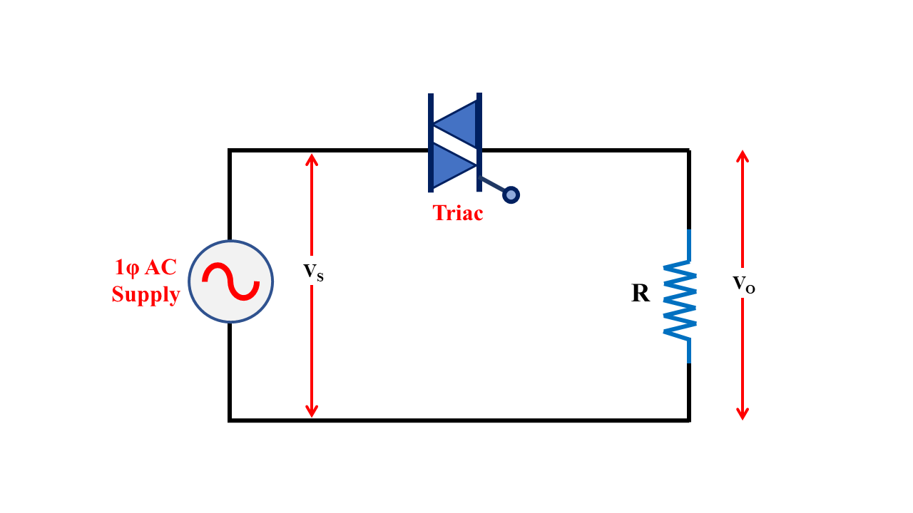
ACVR with triac
  • This configuration is suitable for low-power applications where the load is resistive and has only a small inductance.

ACVR with only one SCR

ACVR with only one SCR
  • This configuration uses 4 power diodes and 1 SCR.
  • In the positive half cycle, diodes D1, D3 and SCR T1 will conduct. During negative half cycle, diodes D2, D4 and SCR T1 will conduct.
  • This configuration is cheaper as only one SCR is used (only one firing pulse circuitry is required)
  • The disadvantage of this configuration is that, at any time, 3 devices (2 diodes and 1 SCR) will be conducting. This causes more voltage drop.