Logo

Thiagarajar College of Engineering
Department of EEE

Power Electronics Virtual Laboratory

What is a Chopper?

Step Down Chopper

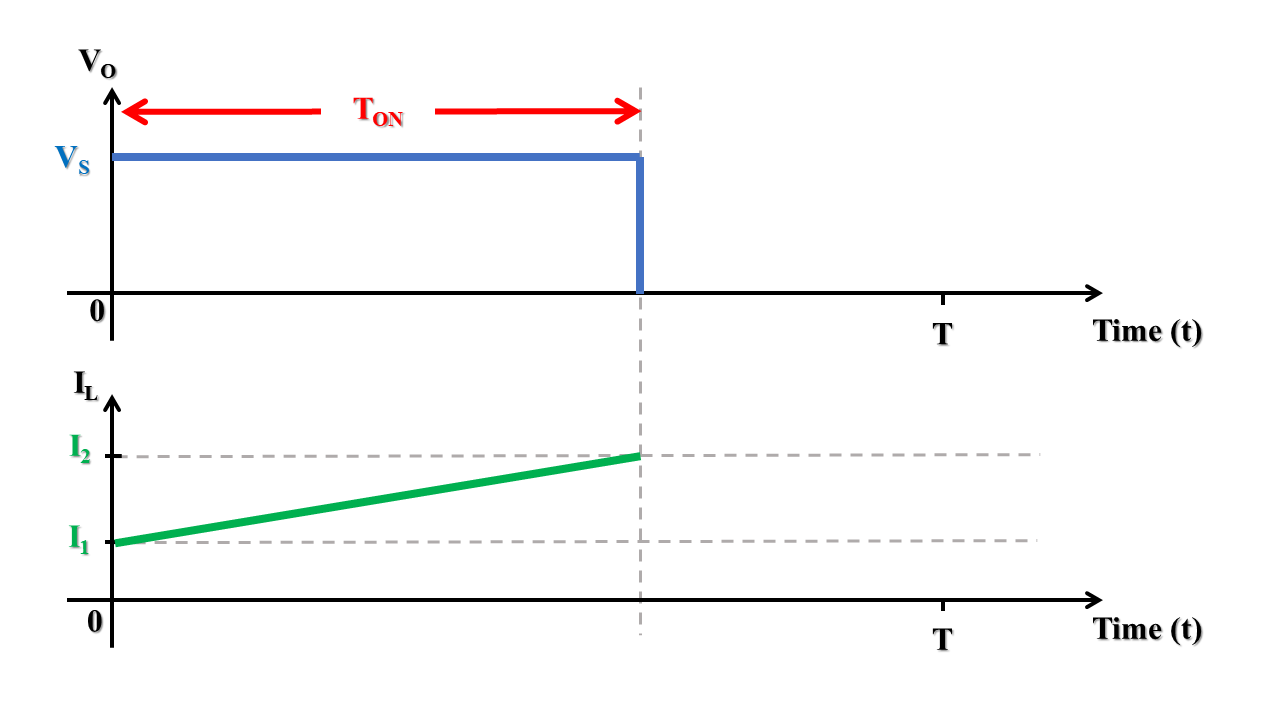
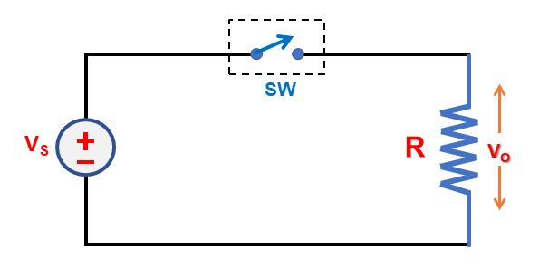
By turning the switch ON and OFF periodically, the voltage source can be connected and disconnected periodically from the load. By this action,chopped load voltage (Vo) as shown, is obtained from a constant DC supply of magnitude (Vs)


Note: The output voltage remains same for any type of load but the load current waveform will be different for different types of loads as explained below


1) For a purely resistive load


2) For RL or RLE loads

Operating Principle of Step-down Chopper

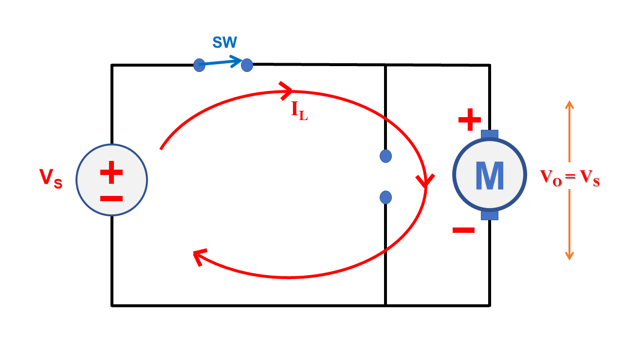
Need for a freewheeling diode in chopper circuit

  • Switch: Turned ON
  • Diode: Reverse biased (does not conducts)
  • Load is directly connected to the source, so Output voltage (Vo) = Input voltage (Vs)
  • The load current (Io) gradually increases and charges the inductor (L) element in the load.

Advantages of DC Chopper

  1. Fast dynamic response: High operating frequencies allow for achieving a faster dynamic response to rapid changes in the load current and/or in input voltage.
  2. High conversion efficiency: Choppers have very low power loss.
    When the switch is ON, voltage drop across the switch is almost zero (Vdiode = 0), so power loss (Ploss) = Vdiode * Iload = 0
    When the switch is OFF, no power is consumed by the load as well as by the chopper.
  3. Compact size: Since choppers can operate at high switching frequencies, the smaller and lighter the transformers, filter inductor and capacitors.
  4. Simple and Smooth control: Since Vo(avg) = D * Vs and duty cycle of the switch can be adjusted steplessly by PWM pulse generator, the output voltage can be varied smoothly.
  5. Less maintainance required
  6. It is Cheaper

Additional Theory

Quadrant of Operation
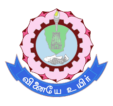
  • The step-down chopper provides positive voltage and positive current at all times. So this is a first quadrant chopper
  • This chopper is also known as Type-A chopper
  • The power flow in type-A chopper is always from source to load (power is positive)
Modes of Conduction

The DC-DC converters can operate in two distinct modes with respect to the inductor current


1. Continuous Conduction Mode (CCM)

  • The state of the converter in which the inductor current is never zero for any period of time is called the continuous conduction mode (CCM).
  • CCM is prefered for high efficiency and good utilization of semiconductor switches and passive components.

2. Discontinuous Conduction Mode (DCM)

  • When the average value of the output current is low (high R) and/or the switching frequency f is low, the converter may enter the discontinuous conduction mode (DCM)
  • In DCM, the inductor current is zero during the portion of the switching period.

For a step-down chopper, the value of the inductance that determines the boundary between CCM and DCM is given by
Lb = (1 - D) R / 2f

Control Strategies

1. Constant Frequency Scheme (PWM Scheme)

  • In this scheme, the ON-time is varied but chopping frequency f (or chopping period T) is kept constant.
  • Variation of ON-time (Ton) means adjustment of pulse width, as such this scheme is called pulse width modulation (PWM) scheme.
  • This scheme is also known as time-ratio control
  • Drawbacks of PWM Scheme:
    1. PWM rectangular voltage and current waveforms can cause turn-on and turn-off losses in semiconductor devices, which limit their practical operating frequencies to the range of 100 KHz.
    2. Rectangular waveforms generate Electromagnetic Interference (EMI)


2. Variable Frequency Scheme

  • In this scheme, the chopping frequency f (or chopping period T) is varied and either ON-time (Ton) is kept constant or OFF-time (Toff) is kept constant.
  • This method is also known as frequency modulation scheme.
  • Disadvantages of frequency modulation scheme compared to PWM scheme
    1. The chopping frequency has to be varied over a wide range for the control of output voltage in frequency modulation scheme. Filter design for such wide frequency variation is quite difficult.
    2. Since frequency variation would be wide, there is a possibility of interference with telephone lines.
    3. The large OFF-time in this scheme may make the load current discontinuous which is undesirable.
Applications of DC-DC converters
  • The dc-dc converters are building blocks of distributed power supply systems in which a common dc bus voltage is converted to various other votlages according to requirements of particular loads. Such distributed systems are common in computer and telecommunication equipment.
  • Step-down choppers are most used in high-performance dc drives, for example, electric traction, electric vehicles, etc
  • Step-up choppers are primarily used in RADAR, ignition systems and power factor applications.
  • Buck boost converters are used in dedicated battery chargers.
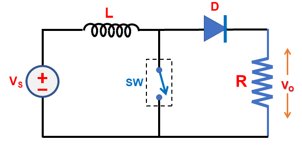
Step-down chopper Vs Step-up chopper
Step-down Chopper Step-up Chopper
Vo = D * Vs Vo = Vs / (1 - D)
When the switch is on, load is directly connected to source.
Vo = Vs
When the switch is on, a short circuit path is created. The output voltage is zero and the inductor charges via the short circuit path.
Vo = 0 V
When the switch is off, load is disconnected from the source.
Vo = 0 V
When the switch is on, the voltage source and charged inductor will supply power to the load together.
Vo = Vs + Vind
Output voltage (Vo) is always lesser than the input DC voltage for all 0 ≤ D ≤ 1 Output voltage (Vo) is always greater than the input DC voltage for all 0 ≤ D ≤ 1